How to read a resistor
Summary
Unlock the mystery of resistors with our comprehensive guide, 'How to Read a Resistor.' Dive into the essentials with an engaging Introduction, demystify the inner workings of resistors, and decode the colorful world of Resistor Color Codes. Discover the significance of Printed Numeric Labels, Letter and Number Codes, and master the art of Measuring and Calculating Resistor Values. Learn troubleshooting tips to tackle resistor value issues like a pro. Your journey concludes with valuable insights in our Conclusion. Ready to amplify your electronics knowledge? Click and explore the fascinating universe of resistors now!
Introduction
Resistors are one of the most fundamental and ubiquitous components found in all kinds of electronic circuits. They restrict and regulate the flow of electric current through their opposition or "resistance" to current. Resistors are used extensively to limit current, divide voltages, pull-up voltages, and dampen signals in circuits. Being able to properly identify, measure, and calculate resistor values is an absolutely essential skill for anyone working with electronics or electrical systems.
Without the ability to accurately determine the values of resistors, circuits can be designed incorrectly and fail to operate as intended. Errors in decoding resistor values can potentially lead to damage of components or even dangerous failures. The purpose of this detailed blog post is to provide a comprehensive guide on how to confidently read, measure, calculate, troubleshoot, and apply resistor values in real-world contexts.
We will start by exploring what resistors fundamentally are, their critical role in electronic circuits, and the physics behind their operation. Next, we will do a deep dive into the various methods used for marking resistor values, including color coding systems, numeric labels, and letter/number codes. Detailed examples will be provided to demonstrate how to decode these resistor value markings flawlessly every time.
Furthermore, we will cover techniques for measuring resistor values with multimeters and calculating required resistances based on circuit parameters. Troubleshooting tips will be provided for deciphering resistors with obscure or damaged markings. By the end, you will have a thorough understanding of determining resistor values for designs ranging from basic hobby circuits to complex industrial systems. Let's get started!

What are Resistors and How Do They Work?
A resistor is a passive two-terminal electrical component that limits current flow through its inherent resistance to the passage of current. The primary function of any resistor is to add a specific value of electrical resistance to a circuit. Resistors are used in electronic circuits to limit current, control signals, regulate voltage, divide voltages, pull-up voltages, and terminate transmission lines. By adjusting resistance values, the characteristics of an electrical circuit can be engineered precisely.
Resistors are categorized into two fundamental types:
Fixed Linear Resistors
These have a set unchanging resistance value. They include common varieties like carbon film resistors, wire-wound resistors, and metal film resistors.
Variable Resistors
These can be adjusted to provide different levels of resistance as needed. Examples include potentiometers, rheostats, and trimmer potentiometers.
The most standard schematic symbol used to represent a fixed linear resistor is a zig-zag line denoting the resistive material inside. Resistors are also sometimes symbolized as simply a rectangular box in schematics. Variable resistors have an arrow added to the zig-zag line to signify their adjustable nature.
The resistance value of any resistor, measured in the unit of the ohm (Ω), represents how much the component opposes the flow of electrical current through it. The relationship between current, voltage, and resistance was discovered by Georg Ohm and is described by Ohm's Law:
Voltage (V) = Current (I) x Resistance (R)
According to Ohm's Law, the potential difference of voltage across a resistor produces an inversely proportional flow of current through the resistor. The current and voltage can be determined for a resistor of known resistance with this fundamental equation. Now let's look at how resistor values are specified.

Methods for Marking Resistor Values
There are several predominant approaches used to indicate the resistance values of resistors:
- Color coding with colored bands
- Printed numeric labels
- Letter and number codes.
The method used depends on the resistor variety and its application environment. Let's look at each of these resistor marking techniques in detail.
Resistor Color Codes
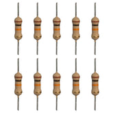
The most common method for denoting resistor values is through a system of colored bands spiraled along the length of the resistor body. This colored band coding system allows resistors of vastly different values to be easily identified through visual inspection alone.
The resistor color code was internationally standardized in the 1920s by the International Electrotechnical Commission (IEC) for precision in electronics manufacturing. The color bands have specific meanings according to the IEC standard:
- The first two colored bands represent the first two significant digits of the resistance value.
- The third band indicates the multiplier to scale the first two digits by.
- The fourth band (if present) shows the tolerance percentage.
For example, a resistor with the colored bands yellow, violet, red, and gold corresponds to a resistance of 4.7 x 10² ohms = 470 ohms with a 5% tolerance according to the resistor color code.
Here is a breakdown of the common colors used in resistor color coding:
- Black: 0
- Brown: 1
- Red: 2
- Orange: 3
- Yellow: 4
- Green: 5
- Blue: 6
- Violet: 7
- Gray: 8
- White: 9
- Gold: ±5% tolerance
- Silver: ±10% tolerance

So if you come across a resistor with the sequence red, red, orange, gold, you can quickly deduce that its resistance is 2,2 x 10³ ohms = 2.2 kiloohms with 5% tolerance. With practice, this color band system allows resistor values to be identified at a glance without needing any additional tools.
Printed Numeric Labels
For resistors with very precise tolerance requirements or high power ratings, color bands may be replaced or augmented by printed numeric labels on the resistor body. This eliminates any ambiguity in decoding the resistance value.
The numeric label will typically consist of a string of 3 or 4 digits denoting the resistor value in ohms (Ω) or kiloohms (kΩ). Commonly used abbreviations include:
- k = kiloohms (x103 Ω)
- M = megohms (x106 Ω)
For example, a resistor labeled "4.7kΩ" has a resistance of 4.7 kiloohms. One labeled "330Ω" has a value of 330 ohms.
This numeric labeling provides an explicit method of displaying the resistance so no decoding is necessary. It is commonly used for high-precision or very small resistors where color bands would be impractical.
Letter and Number Codes
Certain kinds of resistors, especially small surface mount types, are marked using a combination of letters and numbers to convey the resistance value. These combinations are decoded using reference charts specific to the letter/number system.
One common scheme used for surface mount resistors is the EIA E96 series system. It utilizes sequences like "RK73" or "LM211" to identify resistance values and tolerances.
For example:
- RKM 10 = 10 kiloohms (10,000 ohms) with ±10% tolerance
- LM211 = 0.11 ohms with ±5% tolerance
In these letter/number codes:
- R = Stands for "resistor"
- L = Low resistance values
- K = Tolerance of ±10%
- M = Significant resistor value digit
- 73 or 211 = Significant value
Less common coding systems may be manufacturer specific. So decoding them requires looking up resistor code charts. But color coding and numeric labeling remain the predominant methods.
Now that we have thoroughly covered how resistor values are marked, let's go over measuring resistances and calculating required resistor values.
Measuring and Calculating Resistor Values
While marking methods allow reading resistor values by inspection, you will sometimes need to directly measure or derive the needed resistance for a particular circuit application. Here are some important techniques for determining resistor values in these scenarios:
Measuring with a Multimeter
An accurate way to validate a resistor's value is to measure it directly using a digital multimeter in ohms mode. This can identify improperly marked resistors or verify nominal values. Simply touch the meter probes across the resistor terminals and read its measured resistance.
Calculating from Circuit Parameters
Using Ohm's law, the required resistor value for a circuit can be calculated based on the supply voltage and desired current draw:
R = V / I
Where:
R = Resistance value in ohms (Ω)
V = Source voltage across resistor in volts (V)
I = Current through resistor in amps (A)
This allows deriving a suitable standard resistor value to meet circuit requirements.
Measuring In-Circuit
For resistors soldered into a populated circuit board, measure the voltage drop across the terminals to derive resistance with Ohm's Law.
Converting Units
Convert units appropriately between the common scales of ohms (Ω), kiloohms (kΩ) and megaohms (MΩ) based on the needed resistance range.
These techniques allow properly setting and validating resistor values in real-world circuit implementations.
Troubleshooting Resistor Value Issues
When working with resistors in circuits, you may encounter issues determining correct and accurate values in some instances:
Obscured Color Bands
With small or poorly marked resistors, the color bands can become obscured and difficult to discern. Carefully inspect under magnification and bright light to identify faint bands.
Questionable Tolerances
Measured resistances may differ slightly from marked values due to tolerances. Verify with calculations or measurements that resistors are within expected tolerance range for the application.
Overheating
If a resistor is overheating significantly, it may be improperly valued for the circuit. Replace with higher wattage or recalculate needed resistance.
Damaged Markings
Markings on leads can be damaged during soldering or handling. Where possible, trace circuits back to resistors to deduce values before desoldering.
Unknown Coding Scheme
For cryptic resistor markings, lookup charts based on size and design to identify appropriate coding systems.
Leads Snipped Too Short
Resistors leads that are snipped too short become difficult to extract and identify. Leave adequate lead length intact if possible.
Misreading Decoding
With obscure labeling, it's easy to misread codes. Double check decoders and markings to prevent incorrect values.
With experience, you will become adept as an electronics detective at deciphering resistor values through a combination of measurements, deductions, reference materials, and testing. Thoroughly documenting your work is also wise. Let's recap what we've covered.
Conclusion
Resistors are clearly one of the most prevalent components found in all manners of electronic systems and circuits. Understanding how to accurately determine the values of resistors through color codes, numeric labels, and letter/number schemes is an essential skill for anyone involved in electronics.
We first looked at what resistors are, their schematic symbols, and how they electrically resist current based on Ohm's Law. Next, we explored the colored band, numeric labeling, and coding methods used for marking resistor values on their bodies. Examples, decoding tables, and techniques were provided for properly reading these resistor value indications.
Furthermore, we covered directly measuring resistors, calculating required values from circuit parameters, and useful troubleshooting tips for deciphering problem resistors in real-world applications.
You should now have a complete understanding of identifying, verifying, and applying resistor values in your projects. With the knowledge provided in this article, you can tackle any resistor challenge with confidence. Mastering these core skills will make you adept at decoding and leveraging resistor values to optimize your electronic circuits.


