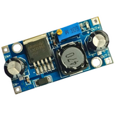
BUCK CONVERTER: LET'S GET STARTED!
What is a Buck Converter?
A buck converter (step-down converter) is a DC-to-DC power converter that steps down voltage (while stepping up current) from its input supply to its output load. It is a class of switched-mode power supply (SMPS) typically containing at least two semiconductors (a diode and a transistor, although modern buck converters frequently replace the diode with a second transistor used for synchronous rectification) and at least one energy storage element, a capacitor, inductor. To reduce voltage ripple, filters made of capacitors (sometimes in combination with inductors) are normally added to such a converter's output and input.
DC/DC buck converter:
DC/DC voltage converter offers a balance of simplicity, flexibility, and ease of use. It features a controller with one or more integrated FETs and an external inductor. Both non-synchronous converters and synchronous converters simplify the design process by reducing the external component count. At the same time, an external inductor allows you the flexibility to optimize your power supply for efficiency, size, or cost.
Basic buck converter:
The fundamental circuit for a step-down converter or buck converter consists of an inductor, diode, capacitor, switch, and error amplifier with switch control circuitry.
The circuit for the buck regulator operates by varying the amount of time in which inductor receives energy from the source. In the basic block diagram, the operation of the buck converter or buck regulator can be seen - the output voltage appearing across the load is sensed by the sense/error amplifier and an error voltage is generated that controls the switch. Typically the switch is controlled by a pulse width modulator, the switch remaining on for longer as more current is drawn by the load and the voltage tends to drop and often there is a fixed frequency oscillator to drive the switching.
Working:
When the switch in the buck regulator is on, the voltage that appears across the inductor is Vin - Vout. Using the inductor equations, the current in the inductor will rise at a rate of (Vin-Vout)/L. At this time the diode D is reverse biased and does not conduct.
When the switch opens, current must still flow as the inductor works to keep the same current flowing. As a result, current still flows through the inductor and into the load. The diode, D then forms the return path with a current Idiode equal to Iout flowing through it. With the switch open, the polarity of the voltage across the inductor is reversed and therefore the current through the inductor decreases with a slope equal to -Vout/L.
Check out a demonstration of the Buck Converter below:


