Automatic Battery Charging Circuit
Summary
Do you want to learn about how battery charging circuits work? If the answer is yes! then check out this blog post which covers the basics of battery charging circuits, discussing the three stages of charging - bulk, absorption, and float - and their corresponding charging parameters. It also emphasizes the importance of CC and CV in battery charging and explores the concept of auto-cut-off circuits. Whether you're a beginner or an expert in electronics, this informative blog is a must-read!
In this blog, we are going to learn about the battery charging circuits and how they work, before everything let’s look at a brief explanation about the battery chargers.
What is a battery charging circuit?

A battery charger circuit is a device used to put energy into a secondary cell or rechargeable battery by forcing an electric current through it. The charging protocol is determined by the size and type of the charged battery. Some battery types can be recharged by connecting to a constant voltage or constant current source; simple chargers of this type require manual disconnection at the end of the charge cycle or may have a timer to cut off the charging current at a set time. Other battery types are unable to withstand prolonged high-rate overcharging; the charger may include temperature or voltage sensing circuits as well as a microprocessor controller to adjust the charging current and cut off at the end of the charge cycle. A trickle charger provides a relatively small amount of current, only enough to counteract the self-discharge of a battery that is idle for a long time. Slow battery chargers can take several hours to charge; high-rate chargers can restore most capacity in minutes or less than an hour, but they usually require battery monitoring to avoid overcharging. For public use, electric vehicles require high-rate chargers; the installation of such chargers, as well as distribution support for them, is a concern in the proposed adoption of electric vehicles.
What are the 3 stages of battery charging?
Three-stage battery chargers are commonly referred to as smart chargers. They are high-quality chargers and are popular for charging lithium batteries. Ideally, however, all battery types should be charged with three-stage chargers, this three-stage charging process keeps the battery healthy.
Before getting into three-stage battery charger circuits, we must understand more about multi-stage battery chargers and why they are used.
Lithium batteries have 3 stages of charging, usually divided into these three stages:
- Constant Current Pre-charge Mode
- Constant Current Regulation Mode
- Constant Voltage Regulation Mode
Sounds similar to a Lead-acid battery? Something different. That’s why we need to buy a new charger for lithium batteries. Moreover, what exactly is “quick charge” and how can it make your battery be charged faster?
The battery charging circuit process consists of 3 stages. There are explained in detail below.
1. Constant Current (CC) Charging
CC charging is a simple method that uses a small constant current to charge the battery during the whole charging process. CC charging stops when a predefined value is reached. This method is widely used for charging NiCd or NiMH batteries, as well as Li-ion batteries. The charging current rate is the most important factor, and it can significantly influence the battery’s behavior. For this reason, the main challenge of CC charging is setting a suitable charging current value that will satisfy both charging time and capacity utilization. A high charging current provides a quick charge but also significantly affects the battery’s aging process. A low charging current provides high capacity utilization but also produces a very slow charge, which is inconvenient for EV applications.
2. Constant-Voltage (CV) Charging
Another method is CV charging, which regulates a predefined constant voltage to charge batteries. Its main advantage is that it circumvents overvoltages and irreversible side reactions, thus prolonging battery life. Since the voltage is constant, the charging current decreases as the battery charges. A high current value is required to provide a constant terminal voltage at an early stage of the charging process. A high charging current from 15 percent to 80 percent SOC provides fast charging, but the high current stresses the battery and can cause battery lattice collapse and pole breaking. The most difficult aspect of CV charging is determining an appropriate voltage value that balances charging speed, electrolyte decomposition, and capacity utilization. In general, the CV charging method is effective for quick charging, but it depletes the capacity of the battery. The negative effect is caused by an increased charging current at a low battery SOC (at the beginning of the charging process), where the current value is significantly higher than the nominal battery current. The high battery current causes the battery lattice frame to collapse and contributes to the pulverization of the active battery pole substance.
3. Constant-Current-Constant-Voltage (CC-CV) Charging
A CC-CV charging method is a hybrid approach that combines the two previously mentioned charging methods. It uses CC charging in the first charging stage, and when the voltage reaches the maximum safe threshold value, the charging process shifts to the CV charging method. The charging process is complete when the current levels off or when full battery capacity is reached. The charging time is mainly defined by the constant current value (CC
mode), while the capacity utilization is predominantly influenced by the constant voltage value (CV mode).
Fundamentals Charging Parameters
Li-ion batteries follow a relatively common charging profile, described in greater detail below. Note that if a charger IC provides configurability, the designer may be able to set their thresholds for these phases. These configurable thresholds are highly beneficial, considering that most battery manufacturers specify certain thresholds for different maximum charge current levels. Configurability can provide an added layer of safety by protecting the battery from over-voltage and over-temperature conditions and overloads, which could permanently damage the battery or degrade its capacity.
1. Trickle charge
Generally, the trickle charge phase is only used when the battery voltage is below a very low level (about 2.1V). In this state, the battery pack’s internal protection IC may have previously disconnected the battery due to it being deeply discharged, or if an over-current event occurred. The charger IC sources a small current (typically 50mA) to charge the capacitance of the battery pack, which triggers the protection IC to reconnect the battery by closing its FETs. Although trickle charging usually lasts for a matter of seconds, the charger IC should integrate a timer that stops charging if the battery pack is not reconnected within a certain amount of time, as this indicates that the battery has been damaged.
2. Pre-charge
Once the battery pack has been re-connected or is in a discharged state, pre-charging begins. During pre-charge, the charger starts to safely charge the depleted battery with a low current level that is typically C / 10 (where C is the capacity (in mAh)). As a result of pre-charge, the battery voltage slowly rises. The purpose of pre-charge is to safely charge the battery at a low current. This prevents damage to the cell until its voltage reaches a higher level.
3. Constant current (CC) charge
Constant current (CC) charge is also considered fast charging, which is described in greater detail below. CC charging starts after
pre-charge, once the battery has reached about 3V per cell. In the CC charge phase, it is safe for the battery to handle higher charge currents between 0.5C and 3C. CC charging continues until the battery voltage has reached the “full” or floating voltage level, at which point, the constant voltage phase begins.
4. Constant voltage (CV) charge
The constant voltage (CV) threshold for Lithium cells is usually between 4.1V and 4.5V per cell. The charger IC monitors the battery voltage during CC charging. Once the battery reaches the CV threshold, the charger
transitions from CC to CV regulation. CV charging is implemented because the external battery pack voltage seen by the charger IC exceeds the actual battery cell voltage in the pack. This is due to the internal cell resistance, PCB resistance, and the equivalent series resistance (ESR) from the protection of FET and cell. To guarantee safe operation, the charger IC must not allow the battery voltage to exceed its maximum floating voltage.
5. Charge termination
The charger IC determines when to terminate the charge cycle based on the current going into the battery dropping below a set threshold (about C / 10) during the CV phase. At this point, the battery is considered fully charged and charging is completed. If charge termination is disabled in the charger IC, the charge current will naturally decay to 0mA, but this is rarely done in practice. This is because the amount of charge going into the battery exponentially decreases during CV charging (since the cell voltage is increasing like a large capacitor), and it would take a significantly longer time to recharge the battery with a very little increase in capacity.
Why are CC and CV important?
CC-CV charging was initially used to charge lead-acid batteries and, later, to charge Li-ion batteries. Li-ion batteries require a much longer CC mode. The CC-CV charging method is more efficient than either the CC or CV methods individually, and as such, it is used as the reference for comparison with the latest charging methods.
The main challenge with CC-CV charging is defining suitable constant values for each model. The suitable current value will provide a balance between charging performance and battery safety. Having a current that is too high or too low can cause negative effects as previously discussed.
Auto-cut off circuits
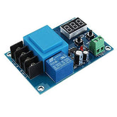
Auto Cut-off – It continuously detects battery charging voltage and once the battery reaches the full charge level, cuts off the charging voltage. We will see the XH-M602 Automatic battery charging cut-off circuit.

The XH-M602 automatic cut-off battery charging circuit works by measuring the voltage on the battery terminal and by breaking the circuits. The XH-M602 module has a transformer and a relay, which are used to break the circuit. In this circuit, we can set the voltage by using the buttons on the board for breaking the charger when the voltage reaches the set value.
Conclusion
In this blog post, we have learned that understanding the battery charging circuit is essential for the proper maintenance and longevity of your batteries. By knowing the three stages of battery charging and the fundamental charging parameters, you can ensure that your batteries are charged efficiently and effectively. Additionally, the importance of CC and CV cannot be overstated in achieving optimal charging results. Lastly, incorporating an auto-cut off circuit can provide an extra layer of safety and convenience in your charging process. By following these guidelines, you can extend the life of your batteries and save yourself time and money in the long run.
If you appreciate our work don't forget to share this post and leave your opinion in the comment box.
Please do check out other blog posts about Popular electronics
Check out other related blog post about batteries What is AH in Battery , Lithium-Ion vs Lithium Polymer Battery , How to Charge LiPo Battery and How to Use IMAX B6 Multifunction Charger for LiPo Batteries
Make sure you check out our wide range of products and collections (we offer some exciting deals!)


